Survey of Overtaking Maneuvers

Project Outline

In cooperation with the TU Dresden, Faculty of Transportation and Traffic Sciences »Friedrich List«, Chair of Road Planning and Road Design, the Fraunhofer IVI has made a contribution to increasing traffic safety. The Federal Highway Research Institute (BASt) is planning the construction of new roads all throughout Germany. In order to make overtaking maneuvers safer on these roads, sight distances, vertical curvatures and street widths must be planned accordingly. The exact figures for these values are taken from an overtaking model, which describes the overtaking behavior of an average driver. The data basis for the detection of model parameters was recorded in 1960 and is thus older than 50 years old today. Due to various developments in vehicle engineering since then, new model parameters are vitally needed. The Fraunhofer IVI and Airclip GmbH have been assigned by the BASt to record overtaking maneuvers in order to create a new data basis for the overtaking model.

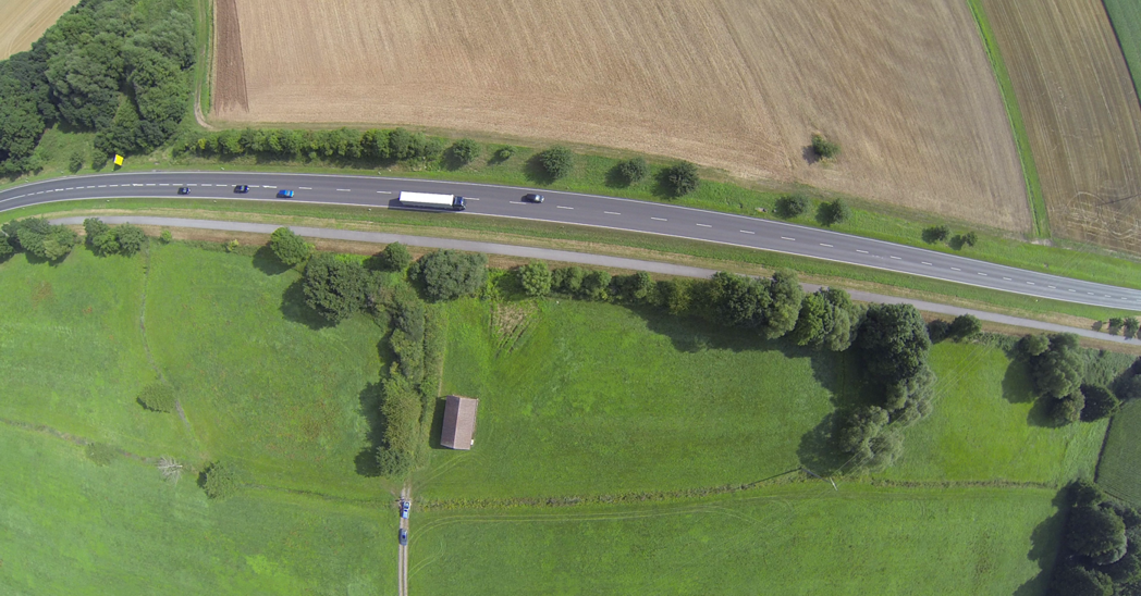
To achieve this, measuring flights are undertaken to various selected overtaking spots. The overtaking maneuvers are recorded using an ultra-wide-angle camera on 800 meters on each of the roads. The camera records 15 pictures with 4096 x 2304 pixels per second, which are rectified and calibrated within an automated downstream process. In the calibrated sequences, individual vehicles can be selected, automatically followed in the video image and their movement trajectories exported. The processing of the images serves to determine both the speed and distance of the vehicles involved in the overtaking maneuver. The algorithms necessary for the processing were developed by the Fraunhofer IVI. Using this method, about 400 overtaking maneuvers have been recorded within a month. More recordings will follow in the near future.

Requirements

In order to acquire appropriate image sequences of overtaking maneuvers on selected routes, the following requirements must be met:

  • Recording of the duration and distance traveled by all parties involved in the overtaking maneuver (vehicle being overtaken, overtaking vehicle, approaching vehicle) as well as the resulting speed and acceleration,
  • Continuous recording of measurement data for all vehicles involved in the overtaking process,
  • Visibility of large road sections of at least 600 meters length,
  • Measurement method not visible to drivers and not influencing driver behavior.

Camera Parameters

For its measurements, the HORUS® multicopter is equipped with an active nick-roll compensated camera module. A gimbal compensates the nick and roll movements of the copter in a way that the mounted camera holds a constant recording angle during the acquisition of the measurement data.

Due to the fact that the maximum flight altitude of HORUS® is 250 meters, and that the respective section must be recorded from a point at this altitude, it is necessary to use a lens with a low focal distance. In addition, the measuring camera has to be calibrated. Calibration means to detect the internal and external camera parameters so that the pixel coordinates can be transformed into the real coordinates of a recorded object.

The detection of internal camera parameters was carried out at the Institute for Photogrammetry and Remote Sensing of the TU Dresden in a room designed especially for the calibration of fisheye lenses. 140 measuring points are located on the ceiling and walls. Their object coordinates are known with a standard deviation of 0.23 millimeters.

Evaluation Algorithm

Overtaking maneuvers are a very important data source for the implementation of algorithms that determine the position of vehicles in the coordinate system using aerial images. Based on the detected vehicle trajectories, the Chair of Road Planning and Road Design of the TU Dresden is designing a model for the overtaking behavior of car drivers. Comprising more than 600 overtaking sequences, the data to be analyzed requires automation to the greatest extent possible.

The results regarding the desired trajectories are combined within post processing. The algorithms for image processing are realized using the development environment Halcon. After calculation of the undistorted images, it is necessary to stabilize them in order to compensate movements made by HORUS®. The subsequent background estimation is the basis for the vehicle detection. During the post processing, faulty detections are removed and the remaining coordinates are matched to the respective vehicles.

The resulting trajectories may be further used, for instance, to design a mathematical overtaking model.

Rectification

The rectification process corrects image distortion by converting each image to central perspective. This procedure facilitates further processing, as the shapes and sizes of objects are independent from their position in the image. The rectification was realized in the Halcon environment, which supports any kind of distortion. After generating a regular grid, which represents the geometry of the image in central projection, each grid point is distorted. With the help of the resulting coordinates and information about the size of the point grid and the original grid spacing, a mapping rule can be derived that realizes the rectification.

The gray-scale value assignment is carried out for each pixel of the export image by bilinear interpolation. In this process, the four adjacent gray-scale values of a calculated pixel position are considered for the interpolation. With its 6200 pixels, the rectified image exceeds the width of the original image by the factor 1.6. With the knowledge about the rectified image, the transformation into world coordinates is now possible. Depending on the project requirements, the measuring range comprises the mapping of a road whose width is low compared to the entire projection surface.

Stabilization

In contrast to a stationary camera, minor image movements caused by a multi-rotor UAV cannot be avoided in spite of the nick-roll compensated camera suspension. In order to determine the positions of vehicles, it is thus necessary to stabilize the image.

In this process, the displacements and rotations between different recorded images have to be detected and corrected. One possible approach to this is to detect and align areas along the roadside that remain unchanged during the measuring process.

A correlation-based matching system provided by Halcon was used in order to find these stationary reference samples. The normalized cross-correlation function was applied as a similarity measure between a given sample and a search area. The calculated area of maximum correlation very probably indicates the location of the reference sample in the image. The results, in turn, form the basis used to generate the search areas for the following images. This procedure reduces the required computing time compared to the consideration of larger, constant search areas.

Correlation-based matching is robust against blurriness and linear brightness changes. On the other hand, the process is sensitive to obscuring as well as to non-linear lighting changes occurring, for example, due to cloudiness. For this reason, the reference samples are automatically updated at regular intervals, so that the image stabilization process can be applied even in weather with variable amounts of clouds.

Background Estimation

For the automatic detection of vehicles in motion, a reference image is needed with which to compare the image under analysis. The background of a scene does not contain any moving objects and is therefore well-suited as a reference. In the establishment of this background image, the following challenges have to be met:

  • During the day, it is very difficult to acquire images of roads with an average amount of traffic that do not contain any vehicles.
  • Due to variable light conditions, the background image is subject to change. This means that there is no static reference image. Therefore, the background has to be estimated and automatically adapted to the changing environmental conditions. Continuous updating of the background image allows for an adaptation to brightness changes.

Because of deviations from the desired viewing angle in case of wind gusts, the perspective distortion of the affected individual images will vary. As a result, the reference image will contain blurred areas along its edges. This effect, which needs to be taken into consideration during vehicle detection, is especially likely to occur at the edges of road markings.

The background estimation algorithm was implemented in the Halcon development environment. Based on the images that are involved in generating the reference image, multi-channel images are produced for each color channel. The calculation of each pixel's mean value across the respective channel with the help of the procedures available in Halcon will present the result of the background estimation.

Vehicle Detection

Provided that only vehicles are detected as moving objects, their positions can be determined. During the detection process, the image under analysis is subtracted from the reference image.

Experience has shown that a transition from the RGB to the HSV color space is of advantage. In contrast to the gray-scale value derived from the RGB image, the utilization of the HSV brightness channel supports a robust vehicle detection, especially if colorful vehicles are involved.

Contiguous areas in the difference image with a higher brightness than a given threshold value produce a binary image which is the basis for further examination. The following general characteristics of the individual areas are to be taken into consideration:

  • A vehicle may be made up of multiple areas,
  • Several vehicles may blend into one larger area,
  • Detected areas may, but do not necessarily have to, belong to vehicles.

In a further step, morphological operators provided by Halcon can be applied to change the shape of the areas. The »closing« operatio ncloses gaps within the areas in order to produce a cohesive vehicle image. To achieve this, first a dilation and then an erosion are executed internally. All detected areas are tested with regard to whether it is plausible that they represent a vehicle.

In order to achieve the desired image resolution, a minimum size of 5x5 pixels and a maximum length of 200 pixels is recommendable.

Filtering and Classification of Vehicle Positions

During post-processing, the independently stored positions are matched with the corresponding vehicles.

This classification procedure was implemented in MATLAB and identifies coordinates that cannot be matched with any of the detected vehicles. Assuming that a vehicle only travels a short distance in the interval between two images, the most probable positions for the description of a specific vehicle path can be found.

The resulting trajectories describe the movements of vehicles at ground level. For a further analysis of the overtaking maneuvers, the investigation of movements in the x-direction is of special interest.